Key Takeaways
- Internal Architecture: Modern fighters utilize a combination of fuselage bladders and integral “wet wing” structures to maximize internal volume while maintaining structural rigidity.
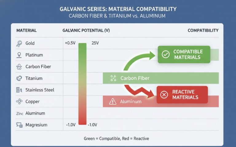
- Conformal Fuel Tanks (CFTs): CFTs bridge the gap between internal capacity and external drag, offering extended range with minimal Radar Cross Section (RCS) penalty compared to drop tanks.
- Thermal Management: In 5th-generation aircraft, fuel acts as the primary heat sink for avionics and hydraulics, requiring sophisticated recirculation systems.
- Survivability: OBIGGS (On-Board Inert Gas Generation System) and reticulated foam are critical for explosion suppression in combat environments.
For defense system integrators and aerospace engineers, understanding fighter jet fuel storage systems is not merely a question of capacity—it is a study in Space, Weight, and Power (SWaP) optimization. Fuel systems in high-performance aircraft dictate combat radius, loiter time, and ultimately, mission success. Unlike commercial aviation, where efficiency is paramount, military fuel architecture must balance range with survivability, center-of-gravity (CG) management during high-G maneuvers, and low-observability requirements.
This technical analysis explores the three primary locations where fighter jets store fuel: internal fuselage/wing assemblies, external jettisonable stores, and conformal fuel tanks (CFTs). We will also examine the subsystem technologies that manage fuel flow, thermal exchange, and inerting.
Internal Fuel Storage Architecture
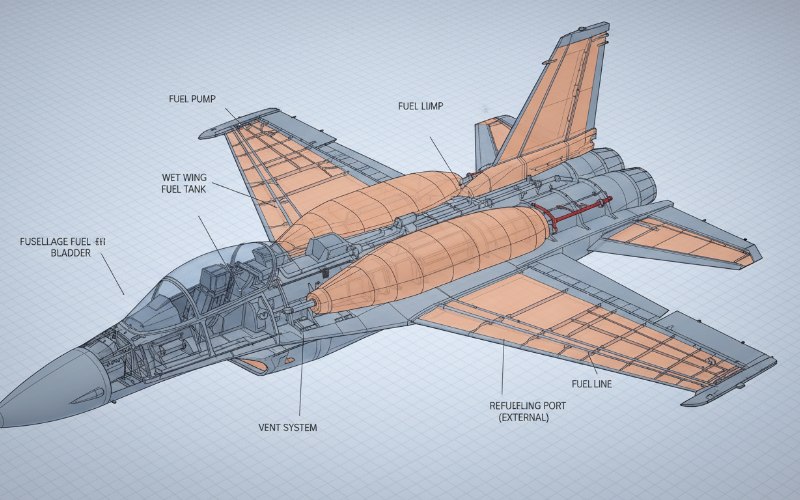
The primary fuel volume of any fighter aircraft is housed within the airframe itself. This is critical for maintaining the aircraft’s aerodynamic profile and, for 5th-generation platforms like the F-35 Lightning II or F-22 Raptor, preserving stealth characteristics. Internal storage is divided into two distinct engineering approaches: Bladder Cells and Integral Tanks.
Fuselage Bladder Cells
Fuselage tanks typically utilize flexible, self-sealing rubberized bladders. These are inserted into structural bays within the fuselage. The primary advantage of using bladders over integral sealing is survivability and maintenance.
- Material Composition: Bladders are constructed from layers of urethane and rubber-impregnated fabric. Self-sealing variants include a layer of un-vulcanized rubber that swells upon contact with fuel, effectively plugging bullet or shrapnel holes.
- Vibration Isolation: The flexible nature of the bladder isolates the fuel containment from airframe flexing and high-frequency vibration, preventing fatigue cracks that could lead to leaks.
- Integration: Bladders are secured to the airframe via lacing cords or snap-fasteners, allowing for removal during heavy maintenance cycles (e.g., Depot Level Maintenance).
Integral Wing Tanks (Wet Wings)
Due to the thin profile of fighter wings, inserting bladders is often spatially inefficient. Instead, engineers utilize “Wet Wing” technology. In this configuration, the wing structure itself—spars, ribs, and skin—forms the tank.
The joints are sealed with high-grade polysulfide sealants to prevent leakage. This maximizes the fuel fraction (ratio of fuel weight to aircraft weight) by utilizing every available cubic inch of the wing box. However, wet wings are more susceptible to leakage from structural flexing and battle damage compared to bladder systems.
External Jettisonable Storage: Drop Tanks
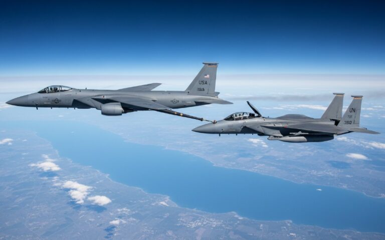
To extend combat radius for ferry missions or deep-strike interdiction, legacy and modern fighters utilize external drop tanks mounted on hardpoints (pylons) under the wings or on the centerline of the fuselage.
Operational Mechanics: Drop tanks are connected via “wet points”—pylons equipped with fuel plumbing and disconnect valves. In a combat scenario, pilots can jettison these tanks to instantly reduce weight and drag, restoring the aircraft’s maneuverability for a dogfight (Within Visual Range combat).
Engineering Drawbacks:
- Parasitic Drag: External tanks significantly increase the aircraft’s frontal area, increasing drag and fuel consumption, partially offsetting the added capacity.
- RCS Penalty: External stores are massive radar reflectors. A stealth aircraft carrying external tanks (non-stealth configuration) compromises its low-observability profile.
- G-Limits: Aircraft carrying full external tanks are often restricted to lower G-forces to prevent structural failure of the pylons.
Conformal Fuel Tanks (CFTs)
The evolution of the F-15E Strike Eagle and the F-16 Block 50/52+ introduced Conformal Fuel Tanks (CFTs) as a standard operational capability. CFTs are additional fuel reservoirs contoured to match the aerodynamic shape of the upper fuselage.
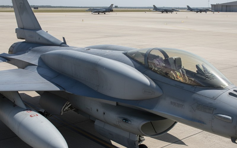
Unlike drop tanks, CFTs are bolted onto the airframe and cannot be jettisoned in flight. However, they offer superior volumetric efficiency. They generate significantly less drag than underwing tanks and free up hardpoints for weapons or sensor pods. For platforms like the F/A-18 Super Hornet and the Eurofighter Typhoon, CFTs represent a critical upgrade path to extend range without compromising payload capacity.
System Engineering: Management and Safety
Storing the fuel is only half the battle; managing it is equally complex. Defense integrators must account for dynamic fluid physics and thermal loads.
Center of Gravity (CG) Control
As fuel is consumed, the aircraft’s weight distribution shifts. If the Center of Gravity moves too far aft, the aircraft becomes unstable; too far forward, and elevator authority is reduced. A dedicated Fuel Management Computer controls transfer pumps to move fuel between tanks automatically, maintaining an optimal CG throughout the flight envelope.
Thermal Management Systems
Modern Active Electronically Scanned Array (AESA) radars and electronic warfare suites generate immense heat. Air cooling is insufficient at supersonic speeds due to aerodynamic heating. Consequently, fuel is utilized as a liquid coolant. Heat exchangers transfer thermal energy from avionics and hydraulic oil into the fuel before it is burned in the engine. This requires complex recirculation logic to prevent the fuel in the tanks from overheating before use.
OBIGGS and Inerting
As fuel is consumed, the empty space in the tank (ullage) fills with vapor, which is highly explosive. To neutralize this threat, modern fighters employ an On-Board Inert Gas Generation System (OBIGGS). This system separates nitrogen from engine bleed air and pumps it into the fuel tanks, displacing oxygen and maintaining an inert atmosphere that cannot support combustion, even if the tank is pierced by an incendiary round.
Technical Comparison: Storage Methodologies
| Feature | Internal Tanks | Drop Tanks | Conformal Fuel Tanks (CFTs) |
|---|---|---|---|
| Aerodynamic Drag | Zero (Baseline) | High (Parasitic) | Low (Interference) |
| Jettison Capability | No | Yes | No (Ground removal only) |
| RCS Impact | None | Significant Increase | Minimal Increase |
| Hardpoint Usage | Internal Volume | Occupies Weapons Stations | Mounted to Fuselage |
| G-Force Limit | 9G+ | Often Restricted (CAT III) | 9G (Platform dependent) |
| Typical Application | Base Mission Fuel | Ferry / Long Range Strike | Range Extension + Payload |
Frequently Asked Questions
Fuel tanks contain internal structures called baffles and one-way check valves (flapper valves). These compartmentalize the tank, preventing rapid fluid shifts that could destabilize the aircraft or uncover the fuel pump inlets (starving the engine). Additionally, many tanks are filled with reticulated polyurethane foam. This open-cell foam acts as a 3D baffle to reduce sloshing and suppresses explosions by dissipating flame front energy.
What prevents fueNo. Aerial refueling probes (or dorsal receptacles for boom refueling) are strictly intake mechanisms. They route fuel directly into the internal and external tanks via a central refueling gallery (manifold). They do not retain fuel after the refueling operation is complete.l from sloshing during high-G maneuvers?
“wet” hardpoint is plumbed to accept fuel from an external tank, allowing it to feed the engine. A “dry” hardpoint provides mechanical mounting and electrical/data connections for missiles or bombs but lacks the fluid coupling required for fuel tanks.
The F-35 was designed with a massive internal fuel fraction (over 18,000 lbs for the F-35A) to reduce reliance on external tanks. This allows it to fly combat missions with a clean, stealthy configuration. However, for non-stealthy ferry flights, it can carry external drop tanks if necessary.